Coupling KS800 for OS(A)85
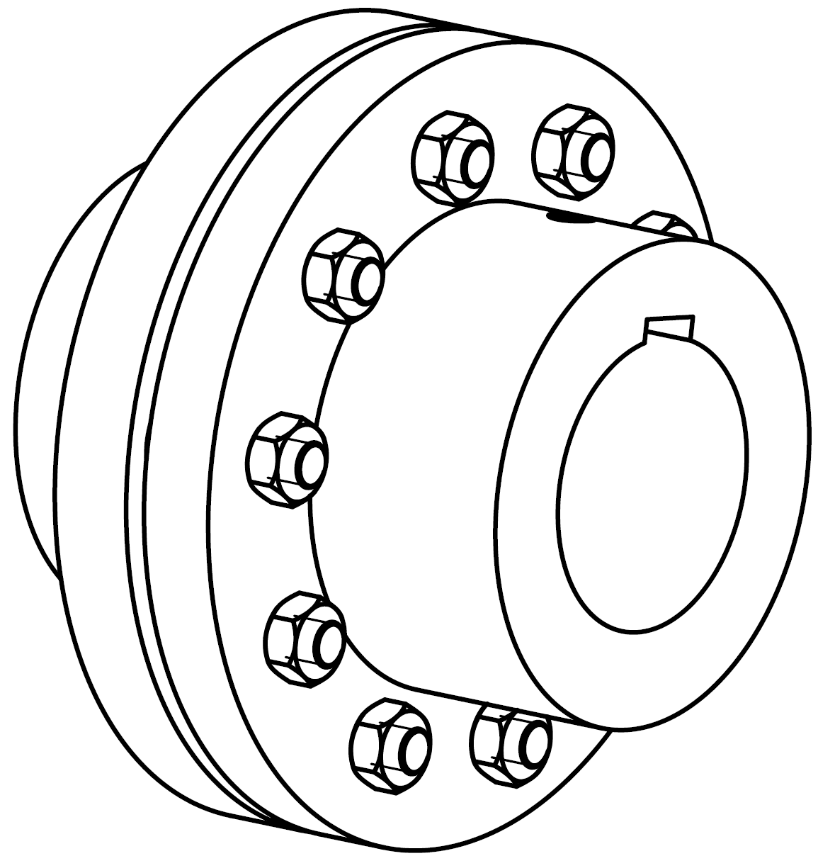
Dimensions:

A | B | C | D | |
|---|---|---|---|---|
KS800, bore for shaft D55 | Ø 55 mm | 14 mm | 16 mm | 59.3 mm |
KS800, bore for shaft D60 | Ø 60 mm | 14 mm | 18 mm | 64.4 mm |
KS800, bore for shaft D65 | Ø 65 mm | 14 mm | 18 mm | 69.4 mm |
KS800, bore for shaft D70 | Ø 70 mm | 14 mm | 20 mm | 74.9 mm |
KS800, bore for shaft D20, pre-drilled | Ø 20 mm | 14 mm | - | - |
Connection positions | ||
|---|---|---|
1 | Compressor side | |
2 | Motor side | |
3 | Compressor shaft | |
4 | Motor shaft | |
Dimensions (if specified) may have tolerances according to EN ISO 13920-B.
The legend applies to all BITZER couplings and includes connection positions that do not exist in every series.
If the motor is different, an individual design of coupling and housing is necessary!
Make sure that the torque transmission between the motor shaft and the coupling half in contact is sufficient (Check torque transmission).