Connections at the compressor
Observe tightening torques for screwed connections according to maintenance instructions AW-100!
HS.95 and OS.A95: additional oil injection
In order to be able to control the oil circulation rate independently of the pressure difference, HS.95 and OS.A95 compressors are equipped as standard with an additional bore with a set screw. If this is opened, the oil circulation rate increases, thus allowing a higher oil injection temperature for the same refrigerating capacity - with slightly reduced compressor efficiency.
When operating at high condensing and low evaporation temperatures, above 50 Hz or 2900 min-1 the oil must be injected at a very low temperature to control the discharge gas temperature to 80°C (standard). Alternatively, to operate the compressor under these conditions with higher oil injection temperatures, the oil volume flow can be increased. For this purpose an additional oil injection into the profiles must be opened.
 WARNING
The system is under pressure!
Serious injuries are possible.
Wear safety goggles!
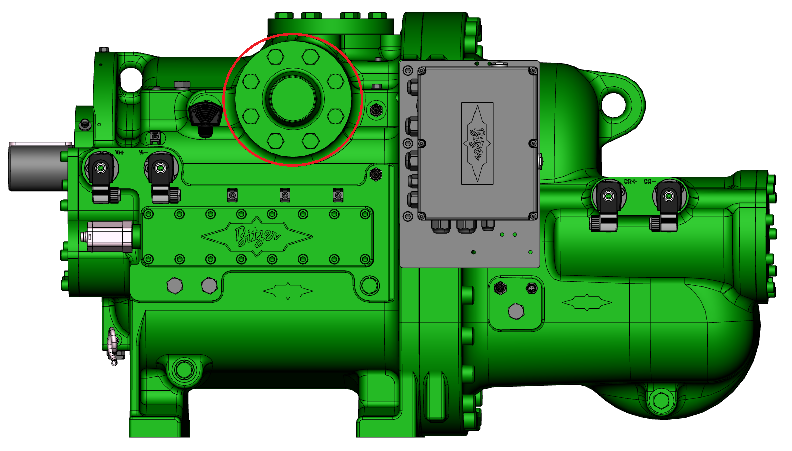
For this purpose
- depressurise the compressor,
- unscrew plug (see illustrations below),
- remove the set screw behind it,
- reinstall plug with new aluminium gasket ring,
- test tightness.


OS.A105: additional oil injection
Similar to HS.95 and OS.A95 (see above), OS.A105 compressors have additional bores with a set screw as standard. Depending on the compressor type and operating frequency, 1 .. 3 of these must be opened - see operating instructions for details:
- SB-520: Operating instructions Open drive screw compressors OS.85, OS.95, OS.105
CSH and CSVH: Connections for external oil coolers
CSH and CSVH compressors have designated connections for external oil coolers. The connection positions for each compressor can be found in the Bitzer Software:
- choose the compressor type
- choose the tab "Dimensions" for dimensional drawings
- choose the tab "Information" for the legend of connection positions
- CSH: Connections for external oil coolers on the rear compressor side, directly below the discharge gas shut-off valve (oval or rectangular flange)
- CSVH: Position 11a and b shows the connections for external oil coolers
CSH: Connection adapter and additional oil injection
Connection adapter:
- CSH65.3 / CSH75.3: Replace oval flange by connection adapter with control valve (option). Connection diameter 16 mm - 5/8" each, kit no. 367 912 01
- CSH85.3 / CSH95.3: Remove rectangular flange and replace with connection adapter with control valve (option). Connection diameter 22 mm - 7/8" each, kit no. 367 912 02
- Connection adapter without solenoid valve on request (if a former type is to be replaced by a CSH.3 without converting the system).
Optional control valves are available, they are integrated in the connection adapter. The control valve opens an additional oil injection nozzle and should be controlled by a thermostat so that it opens when oil cooling is required. Observe the application limits (see Bitzer Software). Details see Operating instructions SB-170.
Due to the additional oil volume (cooler, piping), a solenoid valve may be necessary in the oil line. This is to avoid oil migration into the compressor during standstill. Install the solenoid valve immediately before the oil inlet connection of the compressor, and energise it in parallel to the NO (normally open) contact of the compressor contactor. Recommended additional components:
- sight glass to monitor oil flow
- manual shut-off ball valves in both feed and return lines for ease of service
- oil filter (max. 25 μm mesh size) in case of remote oil cooler or if cleanliness of components is not guaranteed
Up to an additional oil volume (cooler and piping) of 10% of the compressor's standard oil charge and in case of guaranteed cleanliness of components and pipes, these additional measures can be omitted. Deviating layout criteria must be secured by individual checks.
(1): Control valve for additional oil injection, integrated into the adapter (see also schematic wiring diagrams in Technical Information AT-300)
(2): Solenoid valve and oil filter if necessary (see also schematic wiring diagrams in Technical Information AT-300)
CSVH: Special adapter set
A special adapter set is required to connect the external oil cooler. It closes the internal oil ways and ensures an effective oil flow to the oil cooler. For mounting see the following figure.
