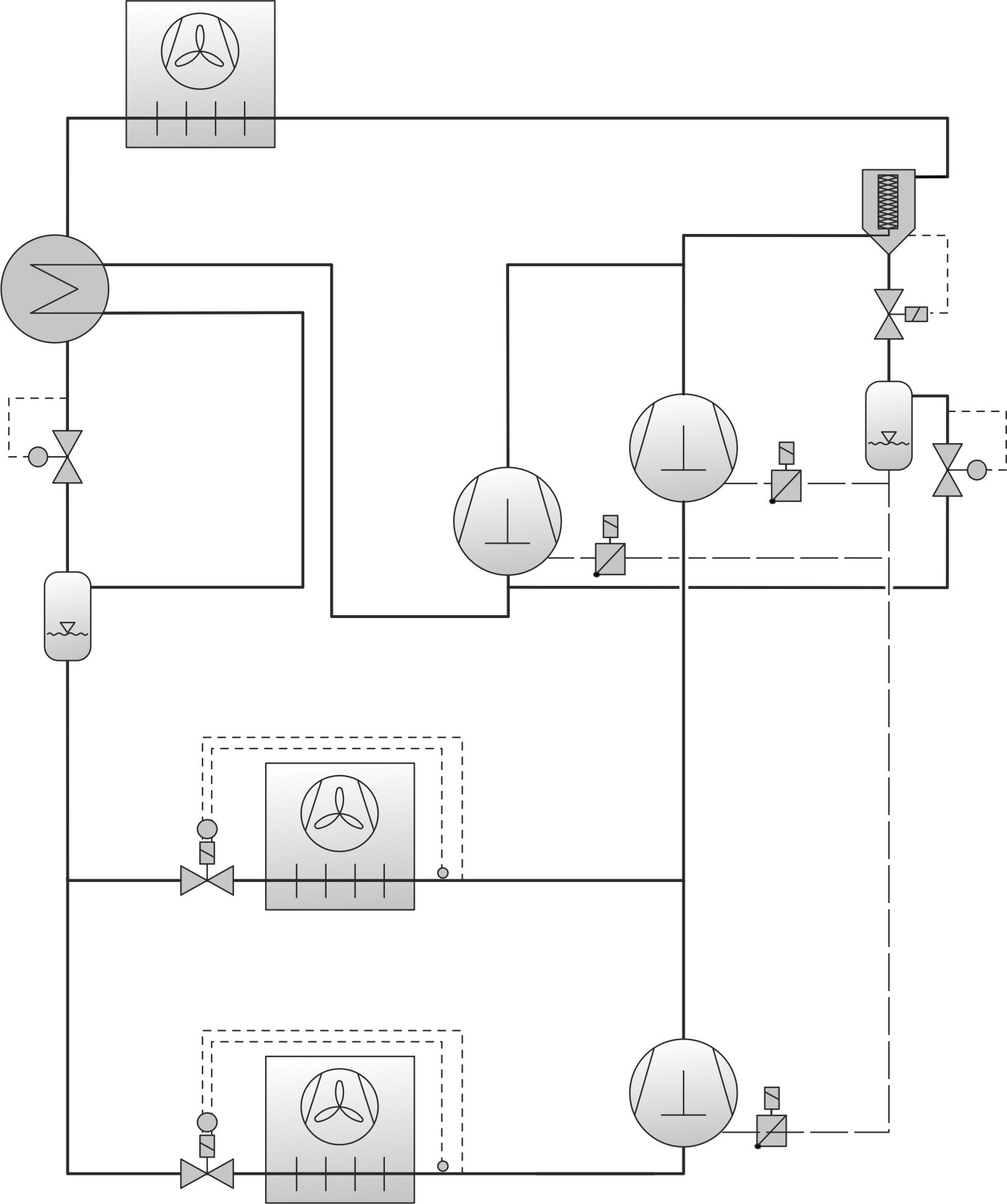
Booster system for medium and low temperature application with parallel compression
- The principle of parallel compression reduces the pressure ratio required to recompress the flash gas to high pressure level. However, it does not reduce the amount of flash gas at intermediate pressure level, nor the losses during throttling.
- The flash gas is thus drawn in at a higher pressure level from a separate parallel compressor or parallel compressor stage which is directly connected to the intermediate pressure vessel.
- Gas and liquid are separated in the intermediate pressure vessel. The liquid is fed as usual to the evaporators of the low and medium temperature refrigeration compressor stages.
- After expansion and heat absorption in the evaporators, the mass flow of the evaporators of the low temperature compressor stage is absorbed by the low temperature compressor stage and compressed again to the suction pressure level of the medium temperature compressor stage.
- The higher efficiency of a booster system with parallel compression is therefore based on a smaller pressure ratio when compressing the flash gas and a higher density of the vapor to be compressed. This means that a lower geometric displacement is required for compressing the vapor drawn from the intermediate pressure vessel.
- Transcritical R744 booster systems with parallel compression typically have four different pressure levels and are composed of:
- The low temperature suction pressure
- the medium temperature suction pressure
- the intermediate pressure
- the gas cooler high pressure
- Each of these are in the respective compressor stages:
- Low temperature compressor stage:
Comprised of low temperature suction pressure and medium temperature suction pressure. The medium temperature suction pressure corresponds to the final compression pressure of the low temperature stage. - Medium temperature compressor stage:
Comprising medium temperature suction pressure and gas cooler high pressure - Parallel compressor stage:
Comprising intermediate pressure and gas cooler high pressure - All compressor stages have a common refrigerating and oil circuit.
- For safety and control, systems with parallel compression need a flash gas bypass valve.
- To ensure a sufficiently high suction gas superheat (3– 5 K at full load in summer) of the flash gas sucked in by the parallel compressor, a liquid suction line heat exchanger should be installed between the gas cooler discharge line and the suction gas line of the parallel compressors.
- This increases the oil sump temperature while reducing the amount of refrigerant dissolved in the oil in the compressor crankcase. This is particularly advantageous when operating the system at low temperatures.
Important points in system planning and system design
- The following criteria may restrict the operation of a booster system with parallel compression:
- The application limits of the parallel compressor(s) at higher suction pressure.
- The minimum possible frequency of the parallel compressor(s) with capacity control (Capacity control with frequency inverter).
- The efficiency of the system is further improved by an optimised intermediate pressure – depending on the high pressure, the gas cooler outlet temperature or ambient temperature.
An optimised intermediate pressure means that the set point for the intermediate pressure is variably controlled. Ideally, it should always be set as high as possible. This allows the parallel compressor(s) to be operated for longer without encountering either of the two limiting criteria mentioned above. At the same time, the efficiency/COP of the system improves. - The transition range from flash gas operation to parallel compression must be determined depending on different load conditions. For operation with heat recovery (HR), all expected operating scenarios or load conditions should be considered ("shop open", "shop closed", with heat recovery (HR), without heat recovery (HR), etc.).
- If parallel compression is not possible, e.g. at medium ambient temperatures, the medium temperature compressors must still be able to deliver the required refrigerating capacity!

application with parallel compression (simplified representation)
parallel compression in the p-h-diagram
Low temperature compressor stage:
1-2 | Compression |
2-3 | Desuperheating |
4-11 | Expansion |
11-12 | Evaporation |
12-1 | Overheating suction gas line |
Medium temperature compressor stage:
1-2 | Compression |
2-4 | Gas cooling/condensation |
4-5 | Internal heat exchanger/subcooling |
5-7 | Relaxation to intermediate pressure |
7-8 | Liquid outlet at the intermediate pressure vessel |
8-11 | Relaxation to evaporation pressure |
11-12 | Evaporation |
12-1 | Total overheating |
7-15 | Gas outlet at the intermediate pressure vessel |
Parallel compressor stage:
21-22 | Compression |
23-21 | Internal heat exchanger/overheating |
24 | Inlet temperature into the gas cooler |