Application with Bitzer compressors
Bitzer does not offer its own soft starters and can therefore only give general recommendations. All Bitzer compressors with motors designed for asynchronous start directly powered from the supply network can be operated with soft starters. With LSPM motors, however, experience has shown that the advantage of combining it with a soft starter is very limited compared to a standard asynchronous motor. In addition, the soft starter must be carefully adjusted, as too low a starting voltage could prevent the LSPM motor from starting.
Type of soft starter
Usually a 3-phase controlled soft starter is advantageous. Furthermore, to avoid potential problems with the rotation direction monitoring of the compressor protection device, an inside delta connection is recommended: It allows the rotation direction monitoring to be connected to the side of the phases not directly controlled by the soft starter. For this, however, the soft starter must not switch on the contactor of the directly controlled phase until directly or shortly before the compressor starts and switch off immediately when the compressor stops or a fault occurs. Otherwise, the module will interpret the operating conditions of the compressor incorrectly. Especially with open drive and semi-hermetic screw compressors, this can lead to incorrect control of the oil solenoid valve (with the risk that the compressor is flooded with oil) or to erroneous fault shutdowns.
Based on customer experience, Bitzer is continuously developing the rotation direction monitoring to make it generally reliable and robust for the various soft starters and configuration options. However, should false shutdowns and difficulties occur, an individual reaction and adapted configuration is possible at least for the compressor modules CM-SW, CM-RC and the SE-i1 protection device. In such a case, please consult Bitzer.
Configuration of the soft starter
First of all, the name plate data of the compressor are decisive.
- For hermetic and semi-hermetic compressors, sizing to the compressor's max. operating current (see name plate) should be sufficient.
- With open drive compressors, experience has shown that in order to ensure a safe start, the soft starter must be significantly oversized due to the necessary construction size resp. the high mass moment of inertia of the external motor.
Many soft starters offer different starting modes and configuration options: from the classic "voltage ramp" and "constant current control" to "current ramp", "torque control", "adaptive control" and special pre-configurations for compressors, pumps or ventilators. Since the different starting modes in turn require the configuration of various further parameters, a general recommendation is hardly possible. If a pre-configuration for compressors is available, this often offers a good result. Alternatively, there is good experience with the "voltage ramp".
The most important parameters for configuration are:
- Voltage/current ramp: The initial voltage of the soft starter is set in % of the nominal voltage or the initial current of the soft starter in % of the nominal operating current. Good experience is available for approx. 40%.
- Ramp/run-up time: If ramp times are too short, the output voltage rises faster than the compressor needs to run up. Unnecessarily long ramp times can lead to malfunctions in the compressor protection device (rotation direction monitoring) and problems with oil management and lubrication. It should be noted that the motor does not necessarily start at the end of the ramp time, but as soon as it receives sufficient current.
- For hermetic and semi-hermetic compressors, approx. 3 s have proven to be useful,
- with (large) open drive compressors, up to 7 s are required for a reliable start.
- Current limitation in % of the max. operating current: To ensure that the motor starts safely, it should be set to min. 300%, with open drive compressors to min. 600%.
- There is no need to set a run-down time, as the compressor comes to a standstill quickly by itself when it is switched off due to the back pressure.
If detailed measurements on the system are possible, the soft starter should be set to minimise the amplitude of the current and the time until the motor starts. The compressor must still start safely even with unfavourable pressure ratios.
If there is no experience with the design of soft starters of the desired type, Bitzer recommends asking the respective manufacturer for support.
Combination with compressor protection devices
Bitzer recommends the compressor protection devices SE-G4, SE-i1 and the compressor module CM-SW for operation with soft starters.
- Reciprocating compressors are equipped with compressor protection devices without rotation direction monitoring.
- Screw compressors: Bitzer recommends the SE-i1 protection device, especially for larger screw compressors, which may require longer ramp times than smaller ones due to their higher inertia. In case of difficulties with the rotation direction monitoring, the corresponding alarms on the SE-i1 can be delayed (after consultation) to ensure reliable operation of the compressor. This is also possible when using the compressor module CM-SW-01. For soft starters with inside-delta connection, there should be no problems if the rotation direction monitoring is connected to the directly connected side of the motor winding - in this case, a normal protection device such as SE-E4 can also be used.
- Scroll compressors: If a protection device with rotation direction and phase failure monitoring is desired, the SE-G4 can be used with soft starters.
More information on protection devices:
- CT-120: Protection devices for BITZER compressors
Compressor protection device may fail after too high voltage has been applied. Possible subsequent fault: compressor failure.
The cables and terminals of the temperature measuring circuit must not come into contact with the control voltage or operating voltage!
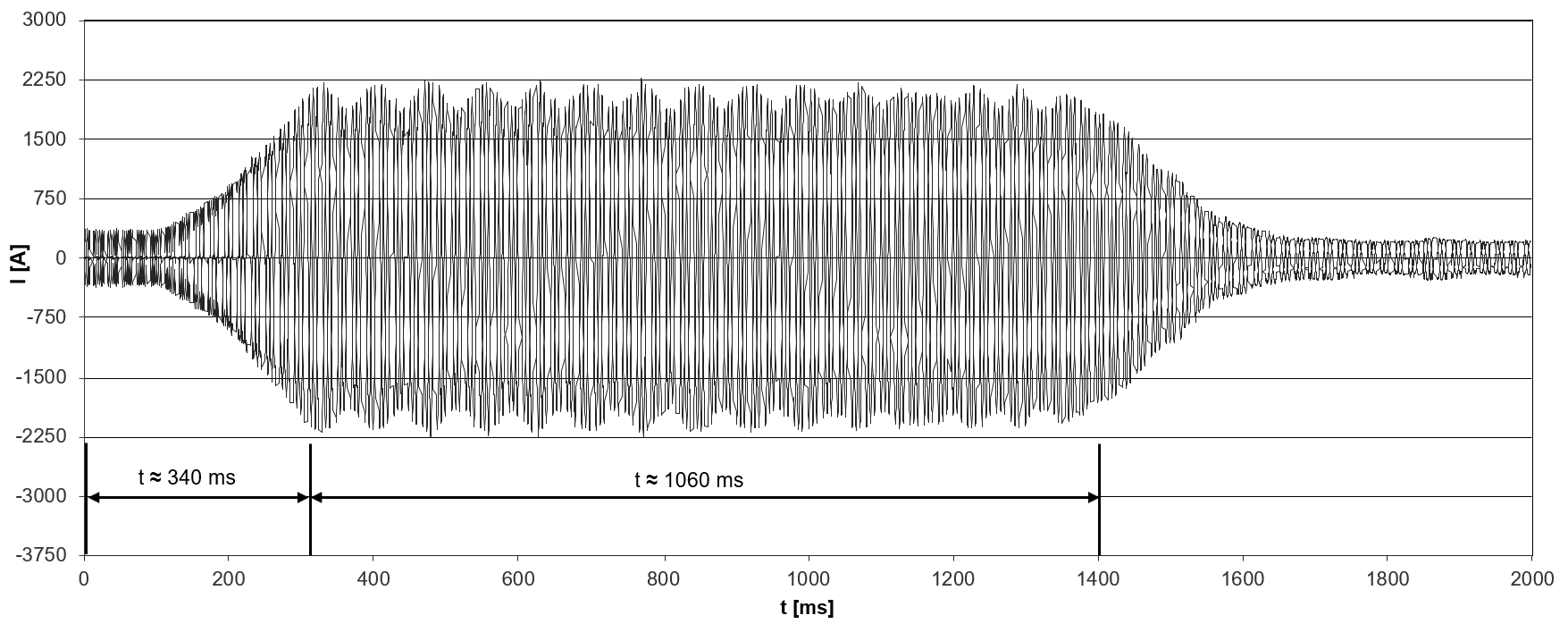
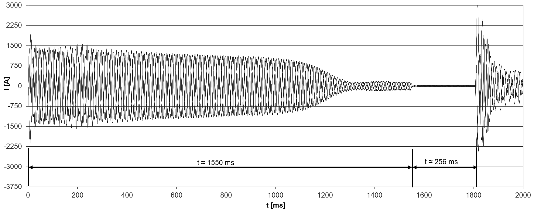
Comparison of starting currents
As an example, the following 2 figures show the starting currents for a typical CS. compressor with soft starter vs. star-delta start. The starting current resulting from the use of the soft starter can vary greatly depending on the type and configuration.
The starting current indicated in the Bitzer Software is the RMS value (root mean square value) of the current. To derive this from the oscillogram, the current must be divided by √2.
Setting in the Best Software
When using the compressor modules CM-RC or CM-SW, they must be integrated according to the schematic wiring diagrams in the Technical Information documents:
- KT-230: Technical information Compressor module CM-RC-01 for reciprocating compressors
- KT-231: Technical Information Compressor module CM-RC-01 for 8FTE-100K .. 8CTE-140K and 8FTE-100Z .. 8CTE-140Z
- KT-240: Technical Information Compressor module CM-RC-02 for reciprocating compressors
- ST-150: Compressor module CM-SW-01 for screw compressors
The starting mode can be set in the Best Software:
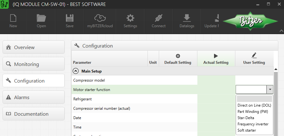
In order to optimally adapt the phase monitoring to the starting mode (frequency inverter or soft starter) and to avoid false shutdowns, the starting mode must resp. can be configured in the future also with the SE-i1.
Arrangement of the wiring in the terminal box of the compressor
 WARNING
Risk of electric shock!
Before performing any work in the terminal box: Switch off the main switch and secure it against being switched on again!
Close the terminal box before switching on again!
In the terminal box cover of Bitzer compressors, an adhesive label shows the possible starting modes and the respective connection of the mains phases to the motor pins. For a start with soft starter (as for a direct-on-line start), the cable bridges supplied may have to be mounted.

Schematic wiring diagrams
In the schematic wiring diagram a start with soft starter is depicted like this, for example:
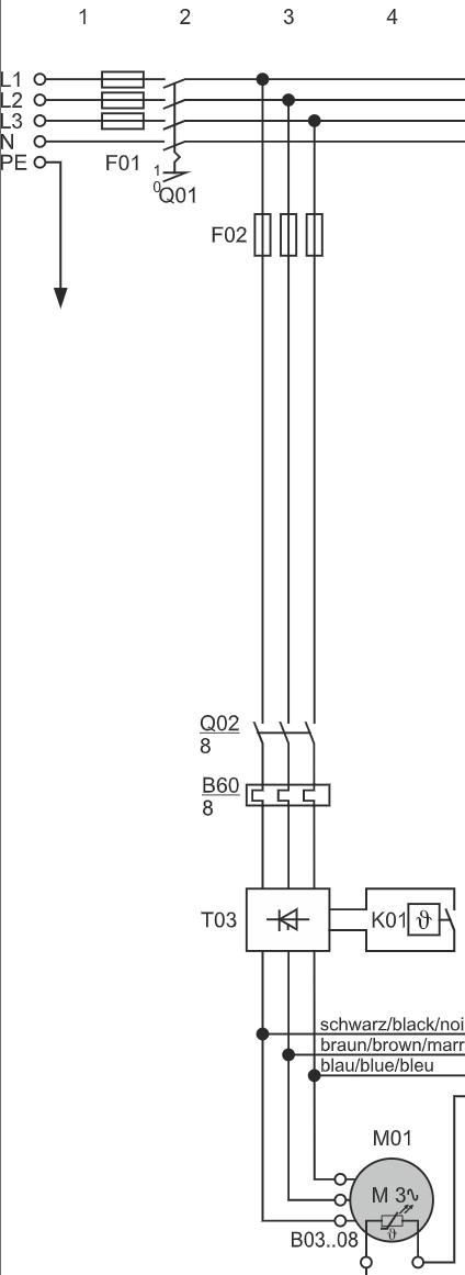
T03: soft starter
Q02: compressor contactor
M01: motor
Schematic wiring diagrams for Bitzer compressors:
- AT-300: Schematic wiring diagrams for BITZER products
Mass moments of inertia for screw compressors
The mass moments of inertia are relevant for the configuration of the soft starter and mey be requested by the soft starter manufacturers.
Compressor | Mass moment of inertia [kg*m²] | |
|---|---|---|
male rotor (driven) | female rotor (not driven) | |
OS. compressors | ||
OS8571 (with coupling) | 0.122 | 0.023 |
OS8581 (with coupling) | 0.138 | 0.023 |
OS8591 (with coupling) | 0.222 | 0.035 |
OS9573 | 0.186 | 0.065 |
OS9583 | 0.204 | 0.076 |
OS9593 | 0.240 | 0.099 |
OS95103 | 0.263 | 0.112 |
CS. compressors (incl. rotor) | ||
CS.6563 | 0.043 | 0.003 |
CS.7573 | 0.087 | 0.012 |
CSH7593 | 0.112 | 0.015 |
CSH8573 | 0.165 | 0.023 |
CSH8593 | 0.183 | 0.025 |
CSH9573 | 0.491 | 0.057 |
CSH9593 | 0.583 | 0.064 |
CS.95113 | 0.700 | 0.060 |
CSW10593 | 1.51 | 0.34 |
HS. compressors (incl. rotor) | ||
HS.9573 | 0.520 | 0.066 |
HS.9583 | 0.586 | 0.076 |
HS.9593 | 0.631 | 0.103 |
HS.95103 | 0.690 | 0.115 |