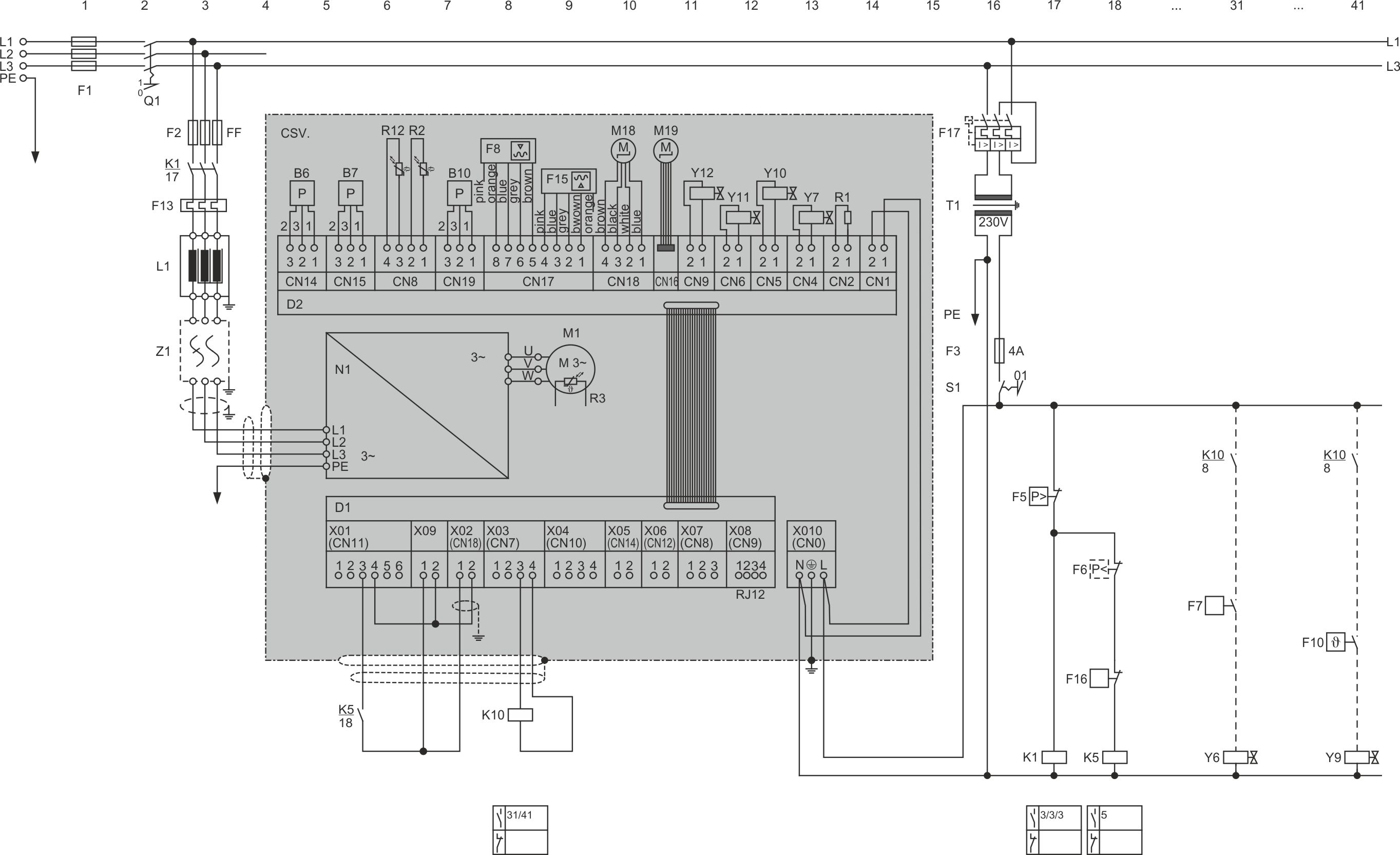
CSV. without STO
Last revision of the wiring diagram:
12.02.2021
Abbr. | Component | |
|---|---|---|
B6 | High pressure transmitter ① | |
B7 | Low pressure transmitter ① | |
B10 | Pressure transmitter at cooling plate outlet | |
D1 | Control board of the FI ① | |
D2 | Extension board of the FI ① | |
F1 | Main fuse | |
F2 | Compressor fuse | |
F3 | Control circuit fuse | |
F5 | High-pressure switch | |
F6 | Low pressure switch | |
F7 | Cut-in delay “ECO" | |
F8 | Oil level switch (minimum oil level)① | |
F10 | Control thermostat for oil cooler | |
F13 | Overload protective device | |
F15 | Oil level switch (maximum oil level) | |
F16 | Relay for protective functions upon customer request (frost protection, water flow, etc.) | |
F17 | Control transformer fuse | |
K1 | Compressor contactor | |
K5 | Auxiliary contactor “compressor is ready-to-operate” | |
K10 | Auxiliary relay “compressor is running” (for message to system controller) | |
L1 | Line reactor ② | |
M1 | Compressor motor ① | |
M18 | Electronic evaporator pressure valve for cooling plate | |
M19 | Electronic expansion valve for cooling plate | |
N1 | Frequency inverter (FI) ① | |
Q1 | Main switch | |
R1 | Oil heater ① | |
R2 | Oil temperature sensor (NTC) ① | |
R3 | Temperature sensor in the motor (NTC) ① | |
R12 | Temperature sensor at cooling plate outlet | |
S1 | Control switch (on/off) | |
T1 | Control transformer (example for 230 V, required according to EN60204-1) | |
Y6 | Solenoid valve "ECO" | |
Y7 | Solenoid valve “LI” (option for CSVH) ② | |
Y9 | Solenoid valve “oil cooler line” | |
Y10 | Solenoid valve “FI cooling” ① | |
Y11 | Solenoid valve "Vi slider +" ① | |
Y12 | Solenoid valve "Vi silder -" ① | |
Z1 | RFI filter ② | |
① | Component included in the extent of delivery of the compressor | |
② | Component can be added as an option to the compressor’s extent of delivery. It can be retrofitted. |
Weiterführende technische Dokumente:
