Modbus introduction
The VARIPACK has a built-in Modbus RTU interface which allows to monitor and control the compressor.
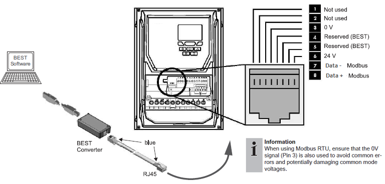
Like the dedicated communication interface for the BEST Software, the Modbus interface is located on the RJ45 socket of the frequency inverter (pin 3, 7 and 8). Whereas the VARIPACKs with enclosure class IP66 (F.Y) have two RJ45 sockets, allowing to plug in the BEST converter and Modbus simultaneously, the VARIPACKs with enclosuree class IP55 (F.W) and IP20 (F.U) have only one RJ45 socket. As a consequence, an adapter cable is required for those types in order to allow to connect the BEST converter and Modbus in parallel. By the F.Y frequency inverters, the two RJ45 sockets are internally bridged, allowing to use both sockets in the same way and for both interfaces.
Configuration of the Modbus communication parameters
Configuration and default settings can be found in BEST under "Configuration" in the parameter group "Modbus".
Setting of the parameters can be done via BEST, the keypad or Modbus. Changing the communication parameters will result in an immediate change of the communication. As the Modbus address is also used as address for the communication of the BEST Software, the connection of BEST will be interrupted when BEST is connected.
Used data types and scaling
Data types:
- int8: signed 8-bit integer
- uint8: unsigned 8-bit integer
- int16: signed 16-bit integer
- uint16: unsigned 16-bit integer
- uint32: unsigned 32-bit integer
- string: string
Scaling of the values:
- Scale 1: The value is the exact value
- Scale 10:
- To transmit a value, it must be multiplied by 10, i.e. 12.3 --> 123
- A received value must be divided by 10, i.e. 123 --> 12.3
- Scale 100:
- To transmit a value, it must be multiplied by 100, i.e. 1.23 --> 123
- A received value must be divided by 100, i.e. 123 --> 1.23
Reading and writing 32-bit values
32-bit values must be read and written as two consecutive Modbus registers (register count = 2).
While Modbus.org has specified that 16-bit values are transmitted with the most significant byte first (or "big endian byte order"), there is no standard for the order of the words that come into play with 32-bit values or character strings with 2 or more registers.
This device transmits 32-bit values with the least significant word first (or "little endian word order").
The following table shows an example of this procedure for the number 123456789, which corresponds to the hexadecimal number 75BCD15.
Register X | Register X+1 | |||
|---|---|---|---|---|
Word 0 | Word 1 | |||
Byte 1 | Byte 0 | Byte 3 | Byte 2 | |
Bit 16 .. 9 | Bit 8 .. 0 | Bit 32 .. 25 | Bit 24 .. 17 | |
Binary | 11001101 | 00010101 | 00000111 | 01011011 |
Hexadecimal | CD | 15 | 07 | 5B |
Reading string values via Modbus
One byte can be used to transmit one character via ASCII code. One word or register therefore allows two characters to be transmitted.
In order to be able to transmit longer character strings, therefore, usually multiple registers are used for the string data type.
The number of registers to be read is listed in "Number of registers".
The character strings are transferred from left to right and always with the most significant word and the least significant byte first (also "big endian word order" and "little endian byte order") .
The following table shows an example of this procedure for the character string ABCD, which is provided in a string with 3 registers.
Register X | Register X+1 | Register X+2 | ||||
|---|---|---|---|---|---|---|
Word 2 | Word 1 | Word 0 | ||||
Byte 4 | Byte 5 | Byte 2 | Byte 3 | Byte 0 | Byte 1 | |
Bit 40 .. 33 | Bit 48 .. 41 | Bit 24 .. 17 | Bit 32 .. 25 | Bit 8 .. 0 | Bit 16 .. 9 | |
Binary | 01000010 | 01000001 | 01000100 | 01000011 | 00000000 | 00000000 |
Hexadecimal | 42 | 41 | 44 | 43 | 0 | 0 |
ASCII | B | A | D | C | ||
Modbus function codes
The following function codes have been implemented from the standard Modbus protocol:
Function | Code (hexadecimal) | Code (decimal) |
|---|---|---|
Read holding registers (H) | 03 | 03 |
Read input register (I) | 04 | 04 |
Write single register (H) | 06 | 06 |
All input registers (I) can also be read as holding registers (H).
Modbus exception codes
The following exception codes have been implemented from the standard Modbus protocol:
Code | Name | Meaning |
|---|---|---|
01 | Illegal function | The function code is not valid. |
02 | Illegal data address | The specified register is not valid. |
03 | Illegal data value | The value is not allowed. |
06 | Device busy | The frequency inverter is busy due to internal data transfer. |
Wiring recommendations
- The cable must be shielded, twisted pair suitable for RS485 communication with a recommended characteristic impedance of 100 .. 130 Ω. The two signal wires must be in the same pair of wires.
- The wiring topology must be daisy chain with 120 Ω termination resistors at each end of the bus line. As this IQ product has no integrated termination resistor, it must be added externally.
- The maximum possible cable length of the Modbus line depends on the used baud rate and the number of devices.
- The Modbus cable should be routed so that the influence from the power cables is minimized. When crossing power cables, a 90° angle should be achieved. Modbus and power cables that run in parallel should be separated by the largest possible appropriate clearance distance, approximately 20 .. 25 cm. A grounded shield plate or grounded metal duct can be used instead.
- The maximum recommended number of IQ products on one Modbus line is 10 devices. If other equipment is connected to the same Modbus line, the maximum current sourcing of the other equipment must be observed.
- The RS485 interface of the VARIPACK is isolated from the power or mains supply respectively, but shares the 0 V potential with the control board (in- and outputs). Data+, Data- and 0 V should be connected between the devices. However, 0 V shall not be connected to ground at any point.
- The shield must only be connected at one end of the bus to avoid unwanted ground current in shielding. However, the shield must be unbroken along the complete bus length, except across galvanic isolated repeaters.
- In case of an isolated client device and non isolated server devices or vice versa, it is recommended to connect the shield at the end without isolation.
- When none of the devices is isolated, the shield should be connected at the client device. When all devices are isolated, it doesn't matter at which end the shield is connected - but it should not be connected to the GND pin of the RS485 interface.
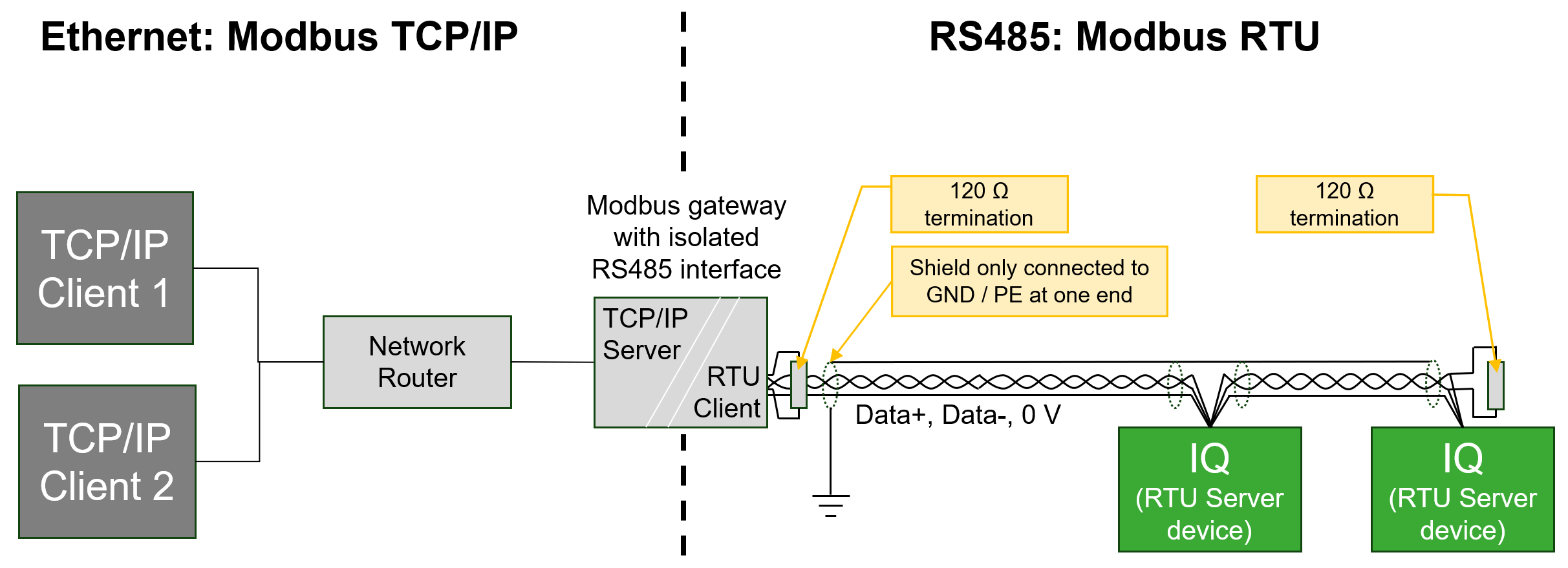
Modbus TCP/IP
In case Modbus TCP/IP is required or preferred over Modbus RTU, a Modbus RTU <-> TCP/IP converter can be used. Gateways are available on the market which translate the Modbus communication 1:1 without requiring to configure the individual protocols/registers in the gateway itself. One product that underwent successful testing at BITZER is the "RS485 TO POE ETH (B)" by Waveshare. In comparison to the standard version "RS485 TO ETH (B)", the POE version provides additional galvanic isolation of the signals and power supply. After configuring the devices as a Modbus RTU <-> TCP/IP converter, multiple IQ products can be made available on Modbus TCP/IP.
In detail, the following settings must be applied by the "VirCom" tool:
- Network
- IP Mode: DHCP (alternatively provide a fixed IP address)
- Work Mode: TCP Server
- Serial
- Baud Rate, Data Bits, Parity, Stop Bits: Must be identical to the communication settings of the connected IQ products.
- Advanced Settings
- Transfer Protocol: Modbus_TCP Protocol
- More Advanced Settings: When configuring the device via the "VirCom" tool, the storage feature (Modbus Gateway Type = Auto query storage type) and multi-host support (Enable RS485 Multi-Host) will automatically be activated. The storage feature will improve the performance for Modbus TCP/IP queries and the multi-host feature allows connecting more than one Modbus TCP/IP client device.