Application with Bitzer compressors
All Bitzer compressors are designed for operation in a wide frequency range and can therefore in principle be operated with frequency inverters. With the Varipack, Bitzer also offers its own frequency inverter. It was specially developed for capacity control of Bitzer compressors and, in addition to speed control, can also cover control and regulation functions of the refrigeration system. In addition, Bitzer offers compressors with integrated frequency inverters:
- Reciprocating compressors Ecoline Varispeed (see brochure KP-100)
- Screw compressors series CSV. (see brochure SP-170)
Information in the Bitzer Software
In the Bitzer Software, many compressors can already be designed with frequency inverter ("Capacity control" - "External FI").

Overload capacity
The frequency inverter needs a certain overload capacity to provide the required starting current and to start the compressor. When designing a VARIPACK in the BITZER Software, this is automatically taken into account. When designing other frequency inverters, the notes in the documents mentioned below should be taken into account.
The starting current of the compressor (FI output side) is compensated on the mains side (FI input side) by the DC link of the frequency inverter. The inverter must provide the starting current with a correspondingly low frequency (and thus voltage). Since the full supply voltage is present at the input of the frequency inverter, the resulting current on the mains side is correspondingly lower. It can be assumed that the line-side current of the frequency inverter does not exceed the maximum operating current of the inverter during compressor start, so that there is no starting current peak.
Detailed information e.g. on permitted frequency ranges and application limits, overload capacity and recommended motor versions can be found in the Bitzer Software as well as in the following documents:
- KT-420: Operation of Bitzer reciprocating compressors with external frequency inverters
- ST-420: Operation of Bitzer screw compressors with external frequency inverters
- EST-420: Operation of Bitzer scroll compressors with external frequency inverters
- CB-110: Operating instructions Varipack – external Bitzer frequency inverters
Compressor and motor damage!
Do not combine a frequency inverter with mechanical capacity control of the compressor! Especially at low speed, adequate motor cooling is not guaranteed because refrigerant mass flow is heavily reduced. Certain exceptions for screw compressors are possible in consultation with Bitzer.
Setting in the Best Software
When using the compressor modules CM-RC or CM-SW, they must be integrated according to the schematic wiring diagrams in the Technical Information KT-230 (for CM-RC) or ST-150 (for CM-SW). The starting mode can be set in the Best Software:
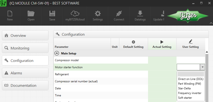
In order to optimally adapt the phase monitoring to the starting mode (frequency inverter or soft starter) and to avoid false cut-outs, the motor starting mode must or can also be configured with the SE-i1 in the future.
Arrangement of the wiring in the terminal box of the compressor
 WARNING
Risk of electric shock!
Before performing any work in the terminal box: Switch off the main switch and secure it against being switched on again!
Close the terminal box before switching on again!
In the terminal box cover of the Bitzer compressors, an adhesive label shows the possible starting modes and the respective connection of the mains phases to the motor pins. For start with a frequency inverter (direct-on-line start), the cable bridges supplied may have to be mounted.
Arrangement of the wiring for reciprocating compressors:
Arrangement of the wiring for screw compressors:
Schematic wiring diagrams
In the schematic wiring diagram the operation with a frequency inverter is e.g. depicted like this:

T02: frequency inverter
M01: motor
Schematic wiring diagrams for Bitzer compressors are compiled in the Technical Information AT-300.