Application with Bitzer compressors
Motors for star-delta start (star-delta motors, Y/Δ motors) are used in some larger compressors, they are e.g.
- standard for screw compressors HS.95 and CS.95 .. 105 as well as reciprocating compressors 8FTE .. 8CTC (for transcritical R744 applications),
- available as option for reciprocating compressors 4VES .. 8FE and screw compressors HS.85, CS.65 .. 85.
Suitable Bitzer motors for star-delta start
For reciprocating compressors those motors may be suitable for star-delta start which are marked in the Technical Information KT-410 with motor code "..D" or "..S" and motor connection "∆" and "Y" (possibly in different lines). In addition, it should be noted whether the specified voltage ranges are available in the voltage network on site. If necessary, please consult Bitzer.
Voltage range | Nominal voltage | Motor code | Motor connection | Nominal voltage | Voltage range |
|---|---|---|---|---|---|
50 Hz | 60 Hz | ||||
220-240 | 230 | 40S | ∆ | - | - |
380-420 | 400 | 40S | Y | 460 | 440-480 |
380-420 | 400 | 70S | ∆ | 460 | 440-480 |
660-720 | 690 | 70S | Y | - | - |
For screw compressors those motors are suitable for star-delta start which are marked in the Technical Information ST-410 with motor code "D" and motor connection "Y/∆".
Voltage range | Nominal voltage | Motor code | Motor connection | Nominal voltage | Voltage range |
|---|---|---|---|---|---|
50 Hz | 60 Hz | ||||
380-415 | 400 | 40D | Y/∆ | 460 | 440-480 |
For a given compressor, an adhesive label in the terminal box cover shows the possible starting modes. For star-delta start, the bridges for direct-on-line start may have to be removed.
Starting current for the design of star-delta start
The starting current shown in the Bitzer Software refers to the measured starting current when the rotor of the three phase motor is blocked (mean value of the currents in L1, L2 and L3, measured simultaneously after 4 s). This starting current (locked rotor) refers to the RMS value (root mean square value): To calculate it, the peak value of the corresponding alternating variable (here current) is divided by √2. The starting current in star (locked rotor) refers to the rated operating voltage in delta wiring. If the motor starts directly in star or delta wiring, these are the maximum starting currents to be expected. However, the first measured amplitude may be larger due to the high unbalances.
With star-delta start, the max. starting current can be reduced to up to approx. 66% of the delta starting current (rotor locked) in the BITZER SOFTWARE. However, this depends on the compressor in question. Furthermore, star phase and transition break must be optimally matched, the IEC connection must be used and start unloading must be correctly applied.
Information in the Bitzer Software
If a specific compressor is selected in the Bitzer Software, the available motors are displayed under "Power supply" - "Power voltage" according to the specified supply frequency (additional motors for North America (UL) under "60Hz UL"). The standard motor is preselected.
The selection corresponds to the specifications in the Technical Information on motor codes (KT-410 for reciprocating compressors, ST-410 for screw compressors, EST-410 for scroll compressors).
All further information concerning the motor can be found in the tab "Technical Data" under "Motor data":

Configuration star-delta start
For star-delta start, 3 contactors are required in the main circuit:
- main contactor: is connected to the 3 phases
- star contactor: sets the star bridge
- delta contactor: establishes the delta wiring
If the duration of the star phase and transition break is not controlled by the compressor module, it must be set correctly. Details can be found in the respective operating instructions (e.g. SB-110, SB-170). In general, the following applies:
CS.65 .. CS.85 | CS.95 .. 96 | CS.105 | HS. | |
|---|---|---|---|---|
Duration of the star phase | 1 .. 2 s | 1.5 .. 2 s | 1.5 .. 2 s | 1.5 .. 2 s |
Duration of the transition break when switching from star to delta operation (incl. reaction time of the contactors) | 60 .. 80 ms | 60 .. 80 ms | 250 ms | 60 .. 80 ms |
With star-delta start, additional start unloading is usually required (Additional start unloading (SU)).
Measuring the real starting current for star-delta start and direct-on-line start in star wiring
The starting current of the compressor must not be measured at the cables between the switch cabinet and the compressor (outlined in red in the picture), because then the current via the star contactor is by mistake measured, too. To avoid this, the starting current should be measured directly at or before the compressor fuse (outlined in green in the picture):

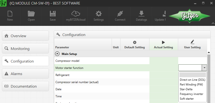
Setting in the Best Software
When using the compressor modules CM-RC or CM-SW, the module controls the contactors for the desired starting mode and, if necessary, the start unloading. For details, see Technical Information KT-230 (for CM-RC) and ST-150 (for CM-SW). The starting mode can be set in the Best Software:
Arrangement of the wiring in the terminal box of the compressor
 WARNING
Risk of electric shock!
Before performing any work in the terminal box: Switch off the main switch and secure it against being switched on again!
Close the terminal box before switching on again!
Make the connections correctly!
Reversed arrangement of the electrical connections leads to a short-circuit!
In the terminal box cover of Bitzer compressors, an adhesive label shows the possible starting modes and the respective connection of the mains phases to the motor pins. For a direct-on-line start, the cable bridges supplied may have to be mounted.
Arrangement of the wiring for reciprocating compressors:
Arrangement of the wiring for screw compressors:
The following figure shows the internal wiring in the motor:
Q02: main contactor (star-delta start) resp. compressor contactor (direct-on-line start)
Q03: delta contactor
Q04: star contactor
(1): bridges for direct-on-line start (optional accessories)
Schematic wiring diagrams
In the schematic wiring diagram a star-delta start is depicted like this, for example:

Q02: main contactor
Q03: delta contactor
Q04: star contactor
M01: motor
Schematic wiring diagrams for Bitzer compressors are compiled in the Technical Information AT-300.